Workshop One: Breadboarding, Ohm's Law & LEDs
Why This Matters
Every phone charger, LED light, and computer you've ever used relies on the same basic ideas you'll practice today. You don't need any prior engineering experience to be here: by the end of this session, you'll have built real, working circuits with your own hands, and you'll have the foundation you need for every SLCCE workshop that follows.
What You'll Do Today
- Learn how a breadboard is organized and how current flows through it
- Build your first closed circuit
- Learn Ohm's Law and why resistors matter
- Light up an LED, and learn why direction matters
- Compare series and parallel circuits
- Learn what "turn-on voltage" means and troubleshoot a real circuit
What You'll Need
Each station is stocked with everything you need for today:
- A breadboard
- Assorted jumper wires
- An assortment of resistors (100 Ω – 10 kΩ)
- LEDs in several colors (red, yellow, green, blue)
You don't need to bring a battery. Power is provided at the power station, where an SLCCE volunteer will connect your breadboard to an Analog Discovery 3 (AD3) once your circuit is ready.
Safety First
This workshop uses only low-voltage power: nothing here can shock you. The worst that can happen is an LED that doesn't light up, or gets a little warm. So experiment freely, and don't be afraid to get something wrong the first time: that's exactly how engineers work. If you're ever unsure about anything, just raise your hand and ask an SLCCE volunteer.
Breadboarding Basics
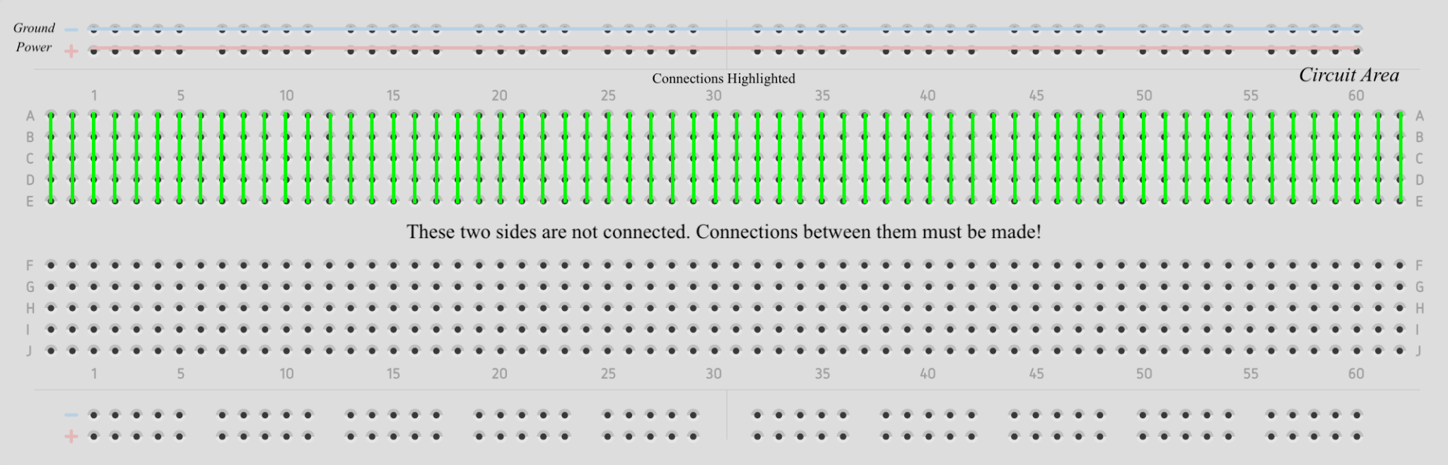
A Breadboard is a handy tool used to build and test electronic circuits. It's a great way to experiment with different circuit designs without any soldering.
A Breadboard has a grid of small holes where you can insert wires and electronic components. On the sides of the breadboard, you'll see long rows marked with (+) and (-) signs. These are called Power Rails, and they're where you connect the positive and negative ends of your power source. The power source is what provides electricity for the circuit.
The rest of the grid is called the Circuit Area. This part is divided into rows and columns. Each horizontal row (usually 5 holes) is electrically connected, so if you place components in the same row, they're connected to each other. The vertical columns along the Power Rails distribute power to different parts of your circuit.
Circuit Elements are the individual components you connect together to build a circuit. There are dozens of different circuit elements; for each one used in this workshop, the table below shows its circuit symbol and its physical form.
| Symbol | Image | Title | Purpose |
|---|---|---|---|
 |
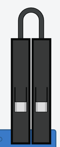 |
Wire (Jumper Wire) | Makes an electrical connection between two points. The color of the wire does not change its properties for this workshop. Wires are not polarized. |
 |
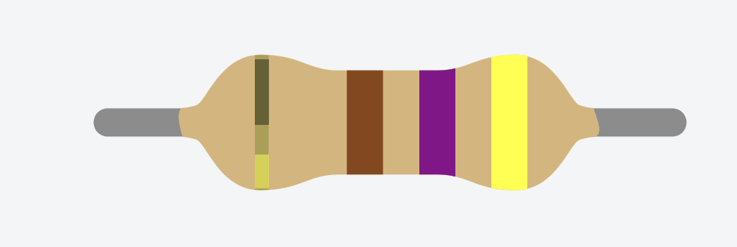 |
Resistor | A special type of wire that has a manufactured resistance. It decreases the current in a circuit, producing heat as a result. Resistors are not polarized. |
 |
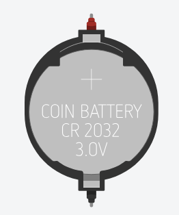 |
Power Source | Any source that can produce a voltage. In this workshop, you'll get power at the power station, where a volunteer connects your breadboard to an Analog Discovery 3 (AD3). Power sources have polarity: current flows out of the positive terminal and back into the negative. |
 |
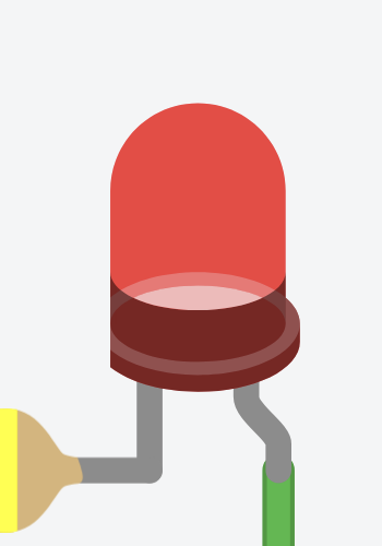 |
LED (Light Emitting Diode) | A special type of diode designed to produce light. A diode only allows current to flow in one direction. LEDs are polarized and MUST be placed correctly or they won't light up. LEDs always require a resistor in series. |
* Polarized means the circuit element must be placed in a specific direction to work correctly.
Open and Closed Circuits
When you build a circuit on a breadboard, you're creating a path for electric current to flow. Current is the flow of electric charge through a circuit, usually measured in amperes (A). A circuit is closed when all parts are properly connected, allowing current to flow. A circuit is open when something isn't connected, and the current won't flow.
Breadboard: Closed (left) vs. Open (right):
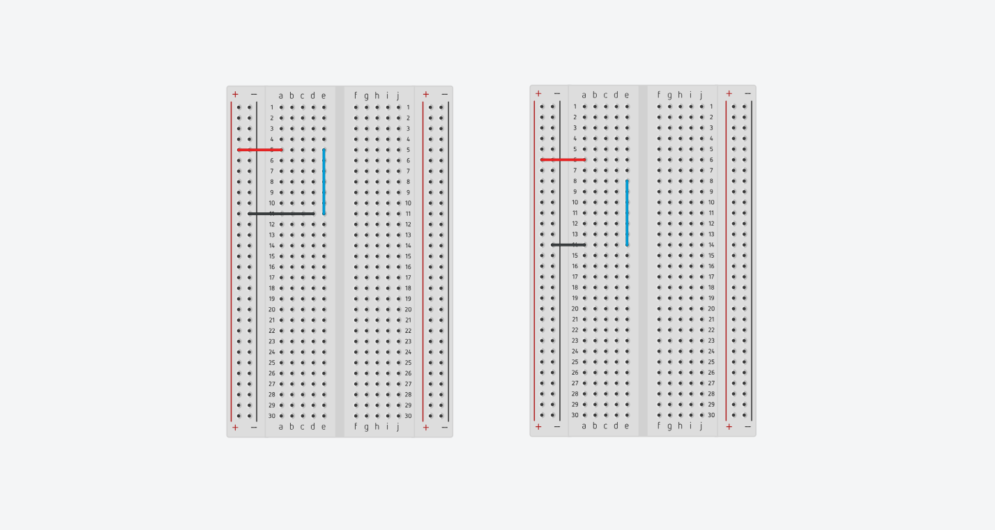
Circuit Diagram: Closed (left) vs. Open (right):

Task 1: Closed Circuit Breadboarding
Assignment
Create your own closed circuit and show it to an SLCCE volunteer to move ahead in the workshop.
Voltage, Current, and Resistance
Ohm's Law
Voltage, current, and resistance are all connected by a single, simple rule called Ohm's Law. Before we look at the formula, here's an analogy that makes it click:
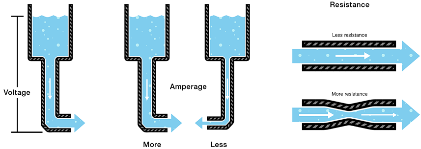
Think of voltage as water pressure, current as water flow, and resistance as the width of the pipe.
For this workshop, we'll assume the voltage supplied by the power source stays constant. If that's true, then resistance and current are inversely proportional: as resistance goes up, current goes down, and as resistance goes down, current goes up, just like a narrower pipe lets less water through.
Just as the width of a pipe controls water flow, a resistor controls current flow. If the water-main pressure is your constant voltage and the water flow is your current, the width of the pipe is your resistance. In this workshop, we use resistors with fixed values: you can think of each one as a manufactured, fixed "pipe width" that sets how much "water" (current) gets through.
Safety Corner
Notice that when resistance drops toward zero, current can become very large: that's exactly what happens in a short circuit, and it's why fuses and resistors matter even in real household wiring. The power supply we use today is far too weak for this to ever be dangerous, but it's a good habit to always ask yourself: "where is the resistance in this circuit?"
LED and Resistor Fundamentals
LED (Light Emitting Diode)
An LED emits light when current flows through it in the correct direction. LEDs are polar devices, so orientation matters.
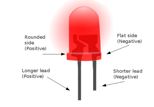
| Anode (Positive) | Cathode (Negative) |
|---|---|
| The longer leg of the LED should connect to the positive side of the circuit. | The shorter leg connects to ground, or the negative side of the circuit. |
Note: An LED placed backward will not light up, since current can only flow one way through it.
Resistors
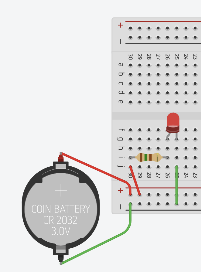
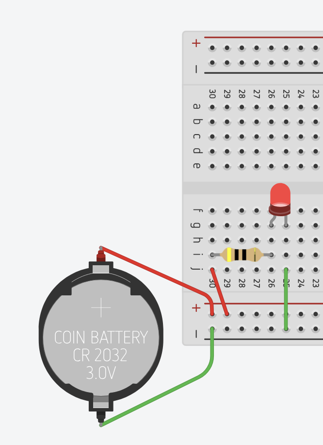
- Purpose: Resistors limit current flow to protect the LED.
- LED Brightness: Inversely proportional to resistance: less resistance means a brighter LED.
| Higher Resistance (Low Brightness) | Lower Resistance (High Brightness) |
|---|---|
 |
 |
Let's Do the Math
Here's why the resistors in your kit are the values they are. Let's size a resistor for a red LED powered at 3.0 V from the power station (AD3):
- Supply voltage: 3.0 V
- Red LED turn-on voltage: about 1.9 V
- Target current: about 10 mA (0.01 A), which is bright but safe for the LED
That's why a ~100 Ω resistor works well for a single red LED at 3 V. Try the math yourself with a different color LED: how does the answer change?
Task 2: LED Circuit
Assignment
Create a closed circuit that powers an LED, then take your breadboard to the power station, where an SLCCE volunteer will connect it to an AD3 to power it up.
Troubleshooting: LED not lighting?
- Check polarity: is the LED facing the right direction?
- Check your connections: do you actually have a closed circuit?
Series and Parallel Circuits
| Figure 1: A series circuit. | Figure 2: A parallel circuit. |
|---|---|
 |
 |
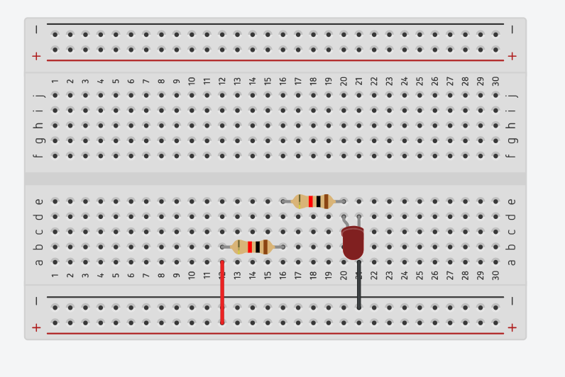
Series Circuits
- Components are connected end-to-end, one after another, along a single path.
- Current (I) is constant throughout the circuit.
- Voltage (V) is divided across the components.
- Total resistance:
Parallel Circuits
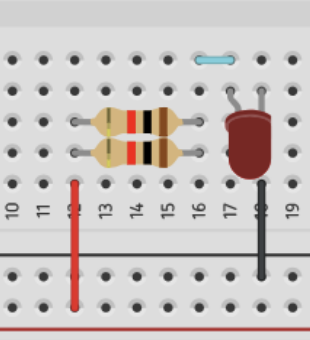
- Components are connected across shared points, creating multiple paths.
- Voltage (V) is the same across all branches.
- Current (I) divides between the parallel branches.
- Total resistance:
Task 3.1
Assignment
Create your own circuit that includes a resistor in series with an LED. When you're ready for your circuit to be checked, notify an SLCCE volunteer.
Task 3.2
Assignment
Using the circuit from Task 3.1, connect a second resistor in parallel with the existing resistor and LED. When you're ready, notify an SLCCE volunteer.
Tasks 3.3 and 3.4
Assignment
Attempt to build Circuits 3.3 and 3.4 shown below. When you're ready for your circuit to be checked, notify an SLCCE volunteer.
Task 3 Circuit Diagrams
| Task 3.2 | Task 3.3 (Challenge 1) | Task 3.4 (Challenge 2) |
|---|---|---|
 |
 |
 |
Task 4.1: Predict and Observe
Assignment
Using the circuit from Task 3.4, replace the red LED with a green LED. What do you notice? Jot down your prediction before you try it: we'll explain what's happening next.
Turn-On Voltage
What Is Turn-On Voltage?
- Turn-on voltage is the minimum voltage needed for an LED to light up.
- If the voltage is too low, the LED won't glow at all, or will be very dim.
- Different LED colors need different turn-on voltages:
| Color | Typical Turn-On Voltage |
|---|---|
| Red | 1.8 – 2.2 V |
| Yellow | 2.0 – 2.2 V |
| Green | 3.0 – 3.2 V |
| Blue | 3.0 – 3.6 V |
These are typical values; the exact turn-on voltage depends on the specific LED, so don't be surprised if your kit measures slightly differently.
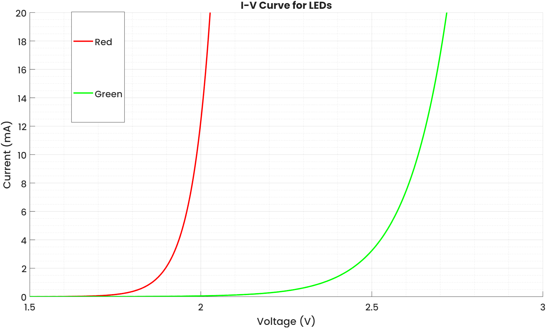
I-V Curve for LEDs: as voltage increases past the turn-on point, current and brightness shoot up quickly.
As voltage increases, the current flowing through an LED increases very quickly once it passes the turn-on voltage. The greater the current, the brighter the light, but keep it under about 20 mA so the LED doesn't burn out.
Why Turn-On Voltage Matters
- It helps you choose the right power source for your circuit.
- It tells you when the LED will start conducting current.
- If you apply too much voltage without a resistor, the LED can burn out.
Task 4.2: Fix the Circuit
Assignment
Now that you know about turn-on voltage, fix the circuit from Task 4.1 so the LED lights up, without changing the LED itself. When you're ready for your circuit to be checked, notify an SLCCE volunteer.
We have resistors ranging from 100 Ω to 10 kΩ available; if you need a different value, just ask an SLCCE volunteer for help!
Glossary
| Term | Definition |
|---|---|
| Voltage (V) | The electrical "pressure" that pushes current through a circuit, measured in volts. |
| Current (I) | The flow of electric charge through a circuit, measured in amperes (A). |
| Resistance (R) | Opposition to current flow, measured in ohms (Ω). |
| Ohm's Law | The relationship \(V = I \times R\) between voltage, current, and resistance. |
| Polarized | Requiring a specific direction to work correctly, like an LED or a battery. |
| Diode | A component that allows current to flow in only one direction. |
| LED | Light Emitting Diode: a diode that produces light when current flows through it correctly. |
| Series Circuit | A circuit where components are connected end-to-end along one path. |
| Parallel Circuit | A circuit where components are connected across shared points, forming multiple paths. |
| Turn-On Voltage | The minimum voltage needed for an LED to start conducting current and producing light. |
| Breadboard | A reusable tool for building and testing circuits without soldering. |
| Power Rail | The rows on a breadboard, marked + and –, used to distribute power. |
Great work today, see you at the next SLCCE workshop!